Inverto’s Unicable II™ Programmer is an essential installation tool helping to configure and diagnose any Unicable II™ LNB or Multiswitch using a PC. The Inverto’s Unicable II™ Programmer software tool for PC provides an easy to use and intuitive graphic user interface allowing the installer to modify the default parameters of the installed Unicable II™ LNB or Multiswitch including for example, the operating mode (Static or Dynamic), the RF/IF frequency mapping grid for Static mode, the IF frequencies of the User Bands, the output power level and the protocols used over each User Band (EN50494/EN50607).
The PC software tool allows to carry out diagnostic tests on the connected LNB or Multiswitch, retrieve diagnostic logs and identify potential installation health issues. The programmer provides several options for updating the firmware or the configuration file of the connected LNB or Multiswitch through the PC. It also features an internal memory that can store a configuration file prepared on the PC and transmit it later to a connected LNB or Multiswitch in the field by pressing a dedicated button releasing the installer from carrying his laptop to the field.
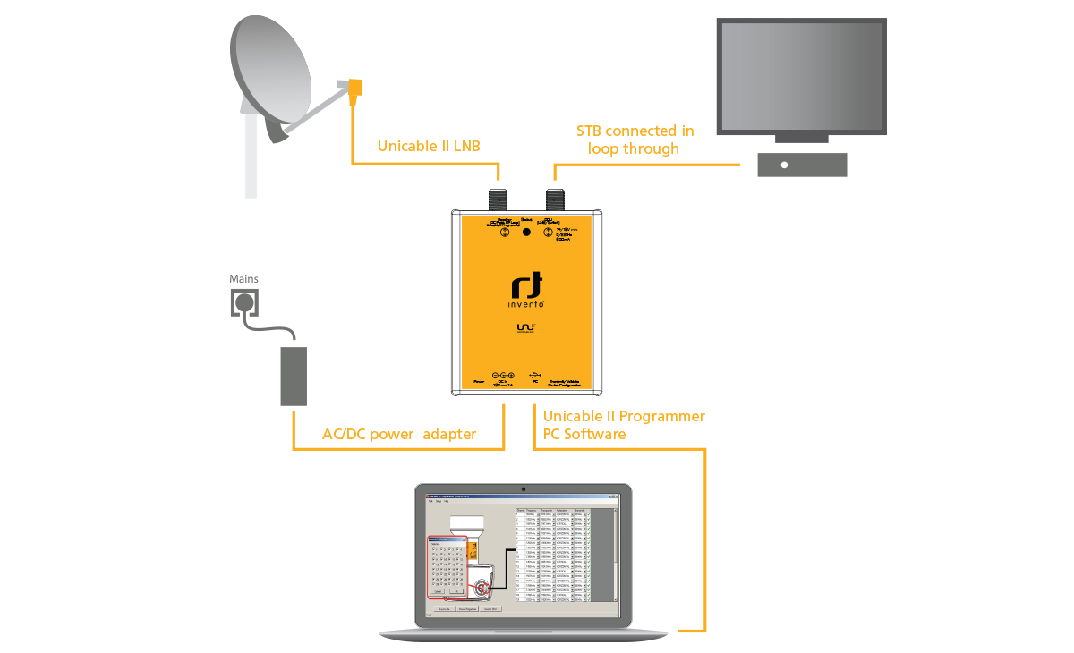
The Programmer device can be integrated into an existing installation, power the LNB or Multiswitch unit using the supplied AC/DC power adapter, and allow a parallel connection to a PC over USB for monitoring and configuration.
The Programmer is supplied with an external AC/DC adapter and a USB cable.
Setup diagram
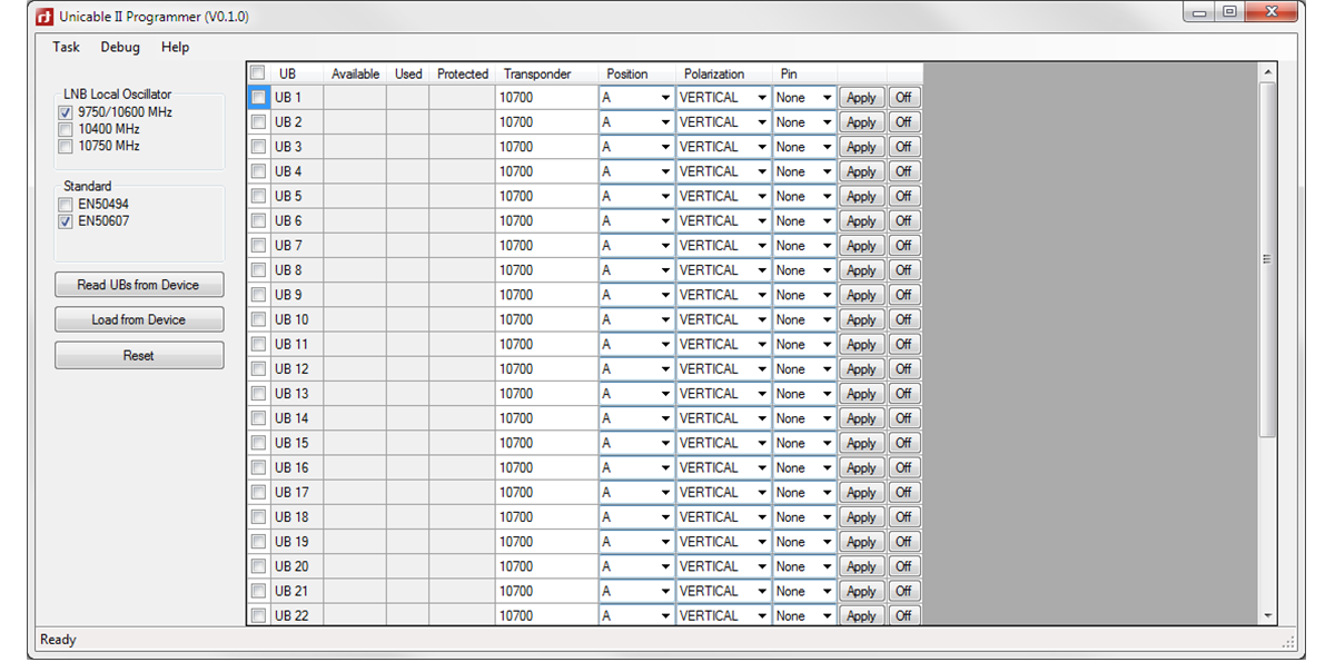
User Band and Protocol testing tool
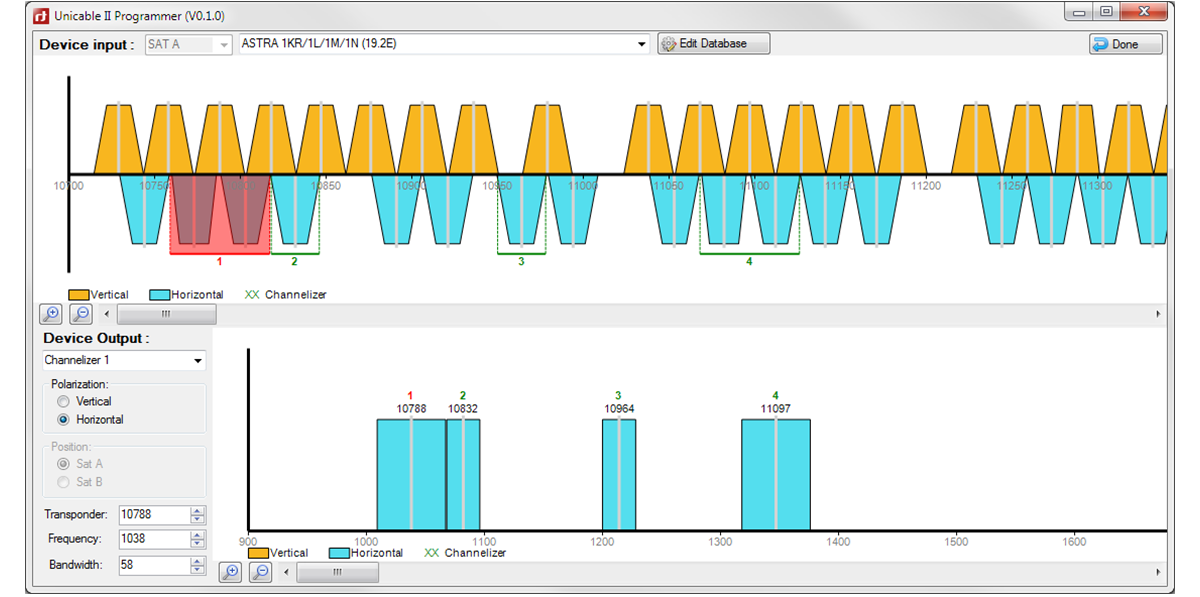
Static mapping editing tool
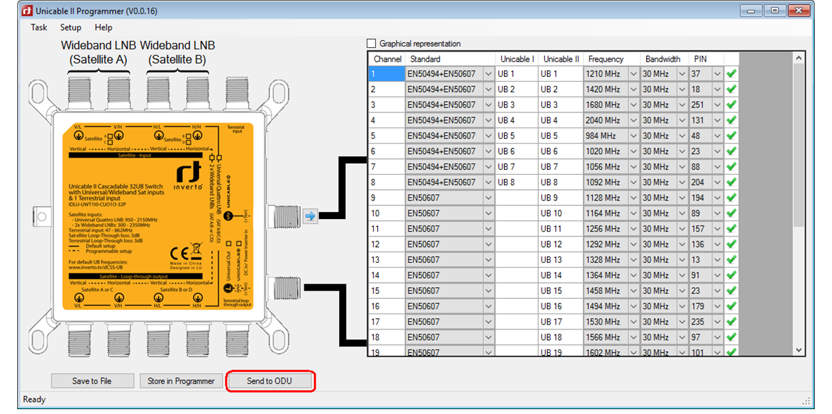
Unicable II™ LNB configuration screen
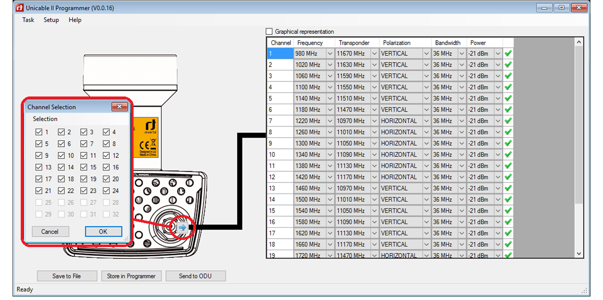
Unicable II™ Multiswitch configuration screen
Setup diagram
User Band and Protocol testing tool
Static mapping editing tool
Unicable II™ LNB configuration screen
Unicable II™ Multiswitch configuration screen
| Technical specifications | |
|---|---|
| Interfaces |
1x Satellite IF, F-type 1x Satellite IF loop-through out, F-type 1x USB (Type-B) |
|
|
|
| Loop-through loss |
1dB max. |
|
|
|
| Control protocols: |
DiSEqC™ commands extension according to CENELEC EN50494 and/or EN50607, DiSEqC2.0. |
|
|
|
| Display and keys: |
|
| Activity LED |
Yellow blinking: Communication activity between ODU and Programmer Green: Configuration files in ODU and Programmer are identical |
|
|
|
| Power LED |
Red: The Programmer is powered over the USB connection Orange: The Programmer is powered over the 12V DC input |
|
|
|
| Button |
Short press: Transmit a configuration file stored in the Programmer to the ODU device Long press: Download the configuration file of the ODU and compare to a file stored in the Programmer |
|
|
|
| Power consumption |
|
| Programmer only |
5 VDC, 50 mA (can be powered over the USB interface) |
|
|
|
| ODU power |
13V ~ 18V, 600 mA max. - powering and programming of an ODU device requires use of the supplied AC/DC adapter |
|
|
|
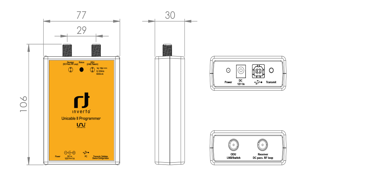
| Dimensions |
107 mm x 77 mm x 30 mm |
|
|
|
| AC/DC adapter |
Input voltage: 100 VAC ~ 240VAC, 50/60 Hz, 0.8 A max. Output voltage: 12 VDC Output current: 2 A Short circuit protection: Yes Low Voltage Directive (2014/35/EU) Electromagnetic Compatibility Directive (2014/30/EU) Eco-Design Directive (2009/125/EC) |


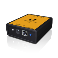
Images

Drawings

PC Software